The operating challenge
One drifting burner can disappear inside the average.
Without burner-level oxygen and temperature data, technicians may have to inspect the entire system to find the source of a change.
Industrial Combustion Monitoring System
See excess oxygen and temperature at each monitored burner. Your team can compare conditions in real time, narrow the search for trouble, and investigate where tuning or maintenance may reduce fuel use.
Start with one furnace, boiler, or equipment group. We’ll review the application and define a practical starting scope.
Why teams can start here
Installed in active manufacturing
The customer is a multibillion-dollar producer with more than 20 manufacturing sites across 10 countries. Its installation gives D.B. Industrial Solutions direct experience in a demanding production environment.
The cost of the blind spot
Firing rate, wear, fouling, air leakage, maintenance, and operating demand can shift combustion conditions. On multi-burner equipment, that change can remain buried until the next inspection, a fuel-cost review, or a larger operating problem brings it to light.
The operating challenge
Without burner-level oxygen and temperature data, technicians may have to inspect the entire system to find the source of a change.
The business difference
Live comparisons help prioritize troubleshooting, tuning, and maintenance. Before-and-after trends help document whether the work changed the condition.
Applications and users
The modular system can monitor one location or scale across a multi-burner installation. Final configuration reflects the equipment, site conditions, integration requirements, and operating objective.
How the system earns its place
The Industrial system connects burner-level measurements to the people and systems that can act on them. The result is a clearer maintenance priority, a record of corrective work, and site data for evaluating economic value.
Compare continuous excess oxygen data and thermal context at individual burners instead of troubleshooting from a system-wide average alone.
Where site conditions are suitable, LoRa moves data between distributed Monitoring Panels, the Ethernet Panel, and the Tuning Device.
Use the Industrial Tuning Device to identify outliers and observe conditions as qualified personnel make adjustments.
Send aggregated measurements through Modbus TCP to plant historians, SCADA, or other infrastructure for trending, review, and reporting.
What happens inside the monitor
Both monitoring platforms acquire oxygen data every 100 milliseconds and temperature data every 1 second. The signal processing steadies the measurements so teams can compare equipment and follow trends with better context.
100milliseconds
A new internal oxygen measurement every 100 milliseconds provides a current view as combustion conditions change.
15samples
The 15-sample moving average refreshes with every valid reading. This smooths brief fluctuations while keeping the measurement responsive.
1second
Each temperature measurement is taken once per second and averages 8 readings for a steadier thermal signal.
These are on-device measurement intervals. Display, network, and BAS update rates depend on the connected interface and system configuration.
At the furnace
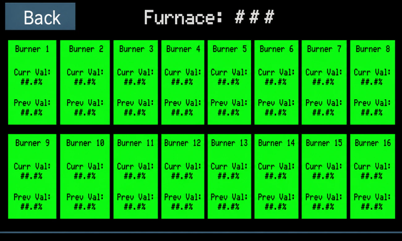
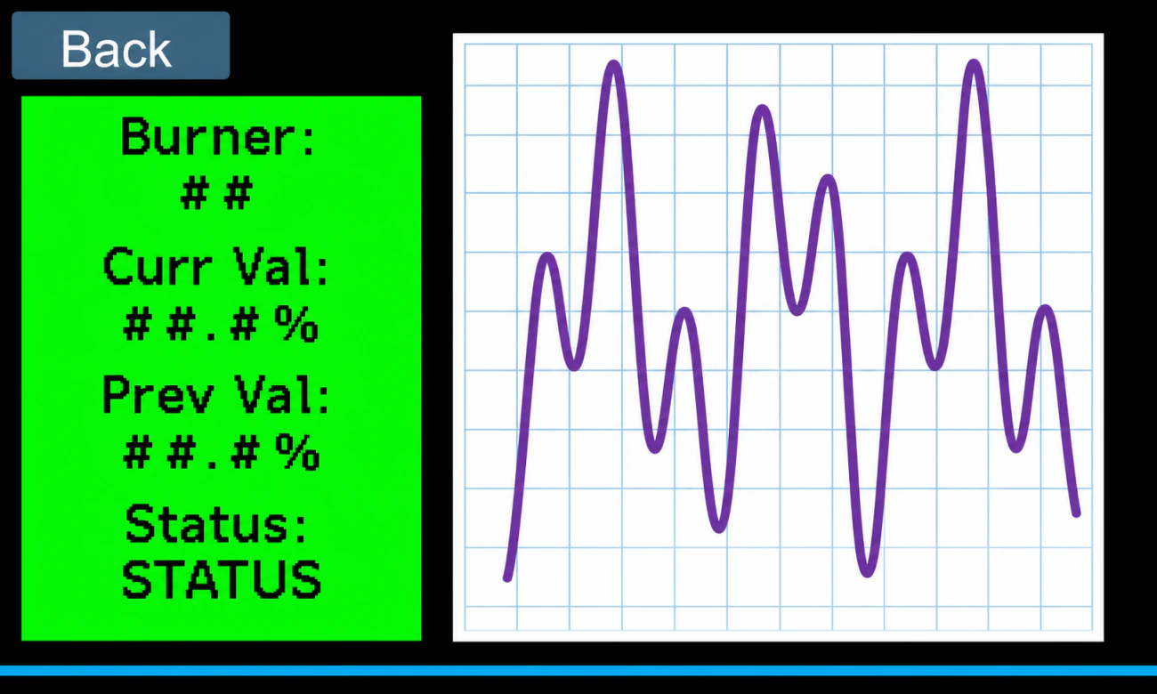
The Industrial Tuning Device shows live oxygen and temperature information at the equipment. Technicians can see which burners stand apart and watch conditions as they work.
System architecture
Monitoring Panels collect local oxygen and temperature. LoRa connects the distributed hardware. The Ethernet Panel and Industrial Tuning Device make the information available to plant systems and field personnel.
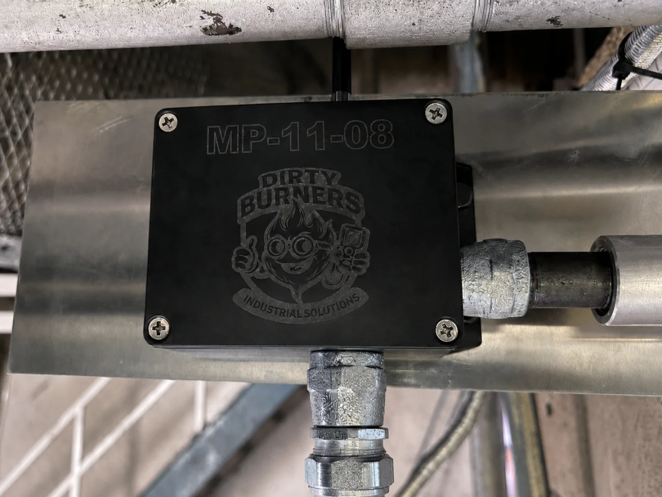
Installed at individual burners or measurement locations to collect excess oxygen and temperature.
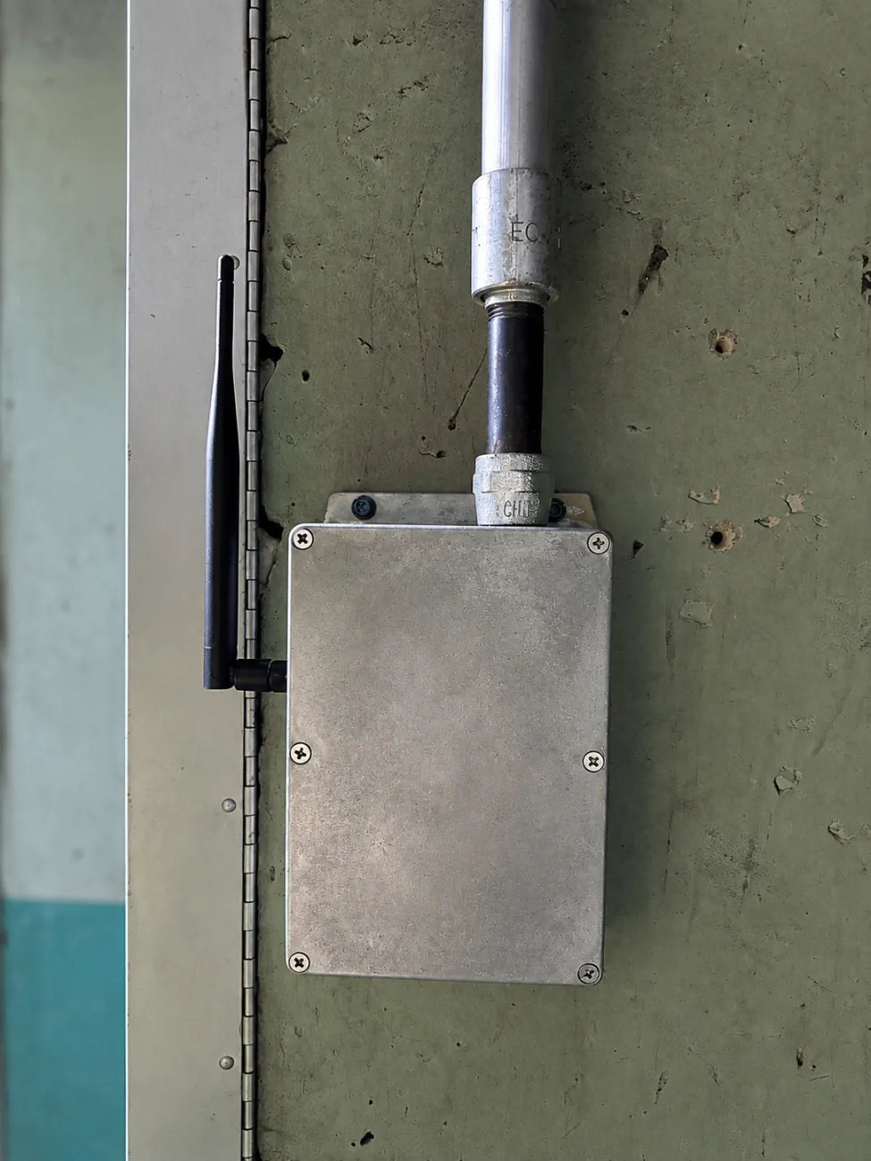
Aggregates module data and exposes it to plant historians, SCADA, or other infrastructure through Modbus TCP.
Displays live burner data so technicians can compare measurements, identify outliers, and observe adjustments in real time.
Deployment and integration
A representative installation lets the plant evaluate reliability, technician usefulness, integration, and economic potential using agreed baseline conditions. Where site conditions are suitable, LoRa can reduce the need for extensive new signal wiring.
Select a boiler, furnace, or burner group where the operating question and potential value are clear.
Confirm measurement locations, safety boundaries, communications, installation, integration, and commissioning.
Measure representative operating conditions and agree on the evidence needed to judge reliability, usefulness, and economic potential.
Review drift, corrective work, integration performance, and site results before deciding whether broader deployment makes sense.
The system does not replace certified burner-management, combustion-control, or safety systems. Those systems remain responsible for safety-critical functions.
Technical review
Final configuration and pricing reflect the monitoring-point count, gateway and tuning-device requirements, site conditions, commissioning, integration, and requested engineering support.
| Component | Part number | Role |
|---|---|---|
| Industrial Monitoring Panel | DBISIMP | Installed at individual burners or measurement locations to collect excess oxygen and temperature. |
| Industrial Ethernet Panel | DBISIEP | Aggregates module data and exposes it to plant historians, SCADA, or other infrastructure through Modbus TCP. |
| Industrial Tuning Device | DBISITD | Displays live burner data so technicians can compare measurements, identify outliers, and observe adjustments in real time. |
OVERVIEW
INTEGRATION
ARCHITECTURE
PILOT
Temperature trends add thermal context to oxygen readings and can help teams recognize changes associated with load, heat transfer, or equipment condition. They do not identify root cause on their own. When a measurement represents flue-gas temperature, a defensible efficiency estimate still requires fuel information.
Industrial FAQs
Application-specific installation, safety, integration, and performance requirements are confirmed during project definition.
It helps teams find combustion outliers sooner, focus troubleshooting, and check whether tuning or maintenance changed the condition. When elevated flue-gas oxygen is caused by excess combustion air, more heat can be carried out through the stack. Oxygen trends can identify a condition worth investigating, but they do not establish a safe target by themselves. Actual savings depend on the starting condition, load profile, fuel cost, and corrective action.
A representative installation can establish the baseline, operating hours, fuel cost, service objective, and success measures. It can then document reliability, integration performance, maintenance usefulness, and any measured change after corrective work. That site evidence gives finance and operations teams a sounder basis for a rollout decision.
Monitoring Panels collect continuous excess oxygen, temperature, and equipment health data at individual burners or measurement locations. Temperature trends add thermal context to oxygen readings and can help teams recognize changing conditions. Excess oxygen and temperature still need to be evaluated with fuel information, operating state, and combustion-air conditions for a defensible efficiency estimate.
Both Industrial and Commercial Monitoring Panels acquire oxygen data every 100 milliseconds and temperature data every second. Each valid oxygen measurement refreshes a 15-sample moving average, while each temperature measurement checks and averages eight readings. Display, network, and BAS update rates depend on the connected interface, polling, and system configuration.
Monitoring Panels communicate with the Ethernet Panel and Industrial Tuning Device over LoRa. The Ethernet Panel aggregates module data and exposes it to plant historians, SCADA, or other infrastructure through Modbus TCP.
The Industrial system is designed as a retrofit monitoring layer. Installation, wireless coverage, mounting, shutdown requirements, and integration scope are confirmed for each site. Existing certified burner-management, combustion-control, and safety systems remain responsible for safety-critical functions.
No. Monitoring provides the oxygen and temperature visibility needed to identify drift and evaluate corrective action. Economic and environmental results depend on the equipment’s starting condition, operating profile, fuel cost, fuel composition, and the actions taken. The system is not a direct carbon-dioxide emissions monitor.
Industrial application review
Share the equipment type, burner count, existing plant systems, and the decision your team needs better evidence to make.
Request an Application Quote